This article will discuss what rigid-flex PCBs are, the advantages of using them, and the rules for designing with them for an application.
What Is a Rigid-Flex PCB?
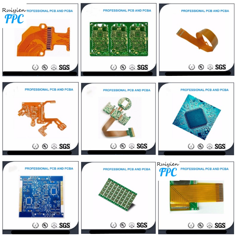
With a rigid-flex PCB, flexible circuit substrates and rigid circuit substrates are laminated together. Rigid-flex PCBs cross the boundaries of traditional rigid PCBs and the unique properties of flex circuits that use high-ductility electrodeposited or rolled annealed copper conductors photo-etched onto a flexible insulating film.
Flex circuits include stackups made from a flexible polyimide such as Kapton or Norton and copper laminated together through heat, acrylic adhesive, and pressure.
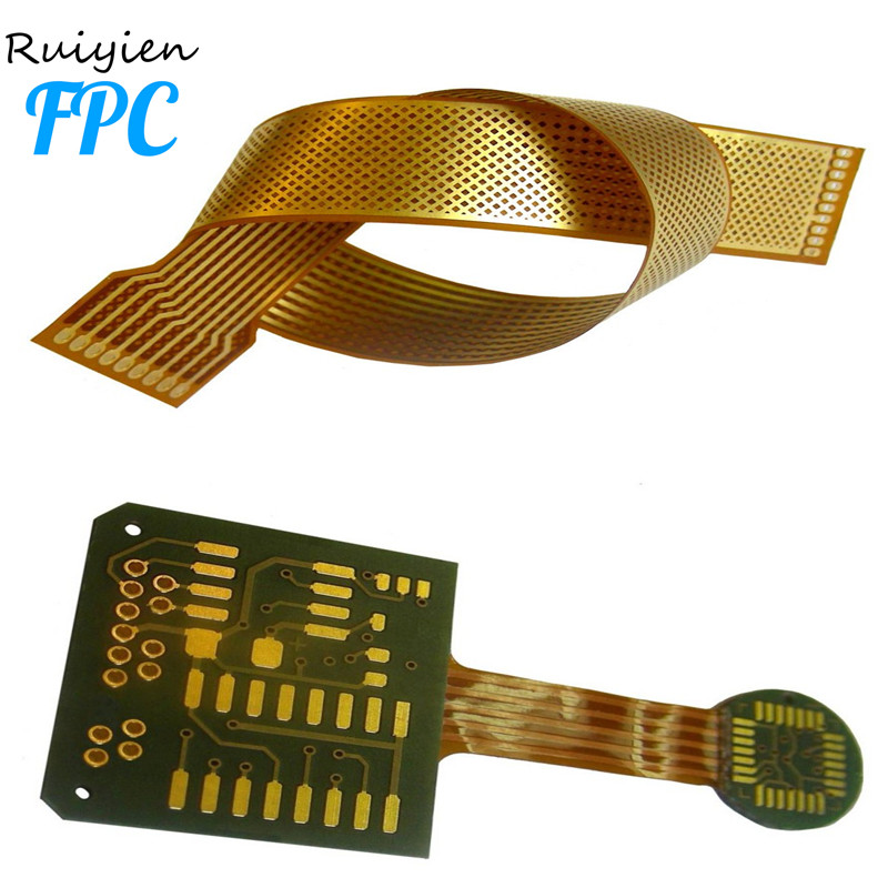
As with conventional PCBs, you can mount components on both sides of the rigid board. Because of the integration that occurs between rigid and flex circuits, a rigid-flex design does not use connectors or connecting cables between the sections. Instead, the flex circuits electrically connect the system together.
The lack of connectors and connecting cables accomplishes several things:
Improves the ability of the circuit to transmit signals without loss
Accommodates controlled impedance
Eliminates connection problems such as cold joints
Reduces weight
Frees space for other components2,4,6
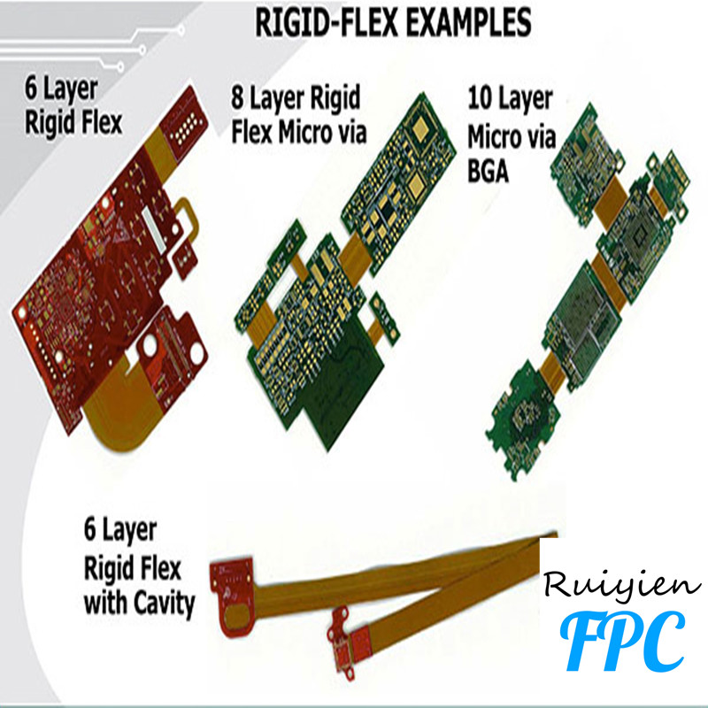
Every rigid-flex PCB is divided into zones that feature different materials and varying layer counts. Rigid zones may have more layers than flexible zones, and materials shift from FR-4 to polyimide in transition zones.
Complex designs often transition from rigid to flex and back to rigid multiple times. As these intersections occur, the overlap of rigid-flex materials requires keeping holes away from the transition zone to maintain integrity. In addition, many rigid-flex designs include stainless steel or aluminum stiffeners that provide additional support for connectors and components.1
For more information on flexible PCBs, check out our article on flexible vs rigid-flex PCBs for project design.
Different Design Rules Apply to Rigid-Flex PCB Design
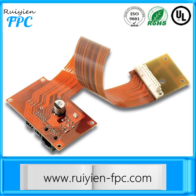
Different challenges offset the versatility and flexibility that allow you to build three-dimensional designs and products. Traditional rigid-flex PCB designs allowed you to mount components, connectors, and the chassis for your product to the physically stronger rigid part of the assembly. Again, in terms of traditional designs, the flexible circuit only served as an interconnect while lowering the mass and improving the resistance to vibration.
New product designs coupled with improved flex circuit technologies have introduced new design rules for rigid-flex PCBs. Your design team now has the freedom to place components on the flexible circuit area. Combining this freedom with a multilayer approach to rigid-flex design allows you and your team to build more circuitry into the design. However, gaining this freedom adds a few challenges in terms of routing and holes.
Flexible circuits always have bend lines that affect routing. Because of the potential for material stress, you cannot place components or vias close to the bend line.
And even when components are properly located, bending flex circuits places repeated mechanical stresses on surface-mount pads and through holes. Your team can reduce those stresses by using through-hole plating and by bolstering pad support with additional coverlay to anchor the pads.2
As you design your trace routing, follow practices that reduce stress on your circuits. Use hatched polygons to maintain flexibility when carrying a power or ground plane on your flex circuit. You should use curved traces rather than 90° or 45° angles and use teardrop patterns to change trace widths.
These practices decrease stress points and weak spots. Another best practice distributes stress across traces by staggering the top and bottom traces for double-sided flex circuits. Offsetting the traces prevents the traces from laying over each other in the same direction and strengthens the PCB.
You should also route traces perpendicular to the bend line to reduce stress. When moving from rigid to flex and back to rigid, the number of layers from one medium to the other may differ. You can use trace routing to add stiffness to the flex circuit by offsetting the routing for adjacent layers
Electromechanical Factors Influence Design
When you design rigid-flex PCBs, think in terms of electromechanical factors that affect both the flex circuit and the rigid board. As you build your design, focus on the ratio of bend radius to thickness. With flex circuits, tight bends or an increased thickness at the bend area increase the chances for failure. Fabricators recommend keeping the bend radius at a minimum of ten times the thickness of the flex-circuit material and building a “paper doll” of the circuit to determine where bends occur.3,6
You should avoid stretching the flex circuit along its outer bend or compressing it along the inner bend. Increasing the bend angle beyond 90° increases stretching at one point and compression at another point on the flex circuit.
Another key issue in rigid-flex reliability is the thickness and type of conductor found in the bend region. You can decrease thickness and mechanical stress by reducing the amount of plating on the conductors and using pads-only plating. The use of heavy copper, gold, or nickel plating decreases flexibility at the bend and allows mechanical stress and fracturing to occur.
Rigid-Flex PCB Design Requires Teamwork
New PCB design tools give your design team the ability to manage multiple layer stacks, visualize 3D electromechanical designs, check design rules, and simulate the operation of flex circuits. Even with these tools in hand, the successful design of a rigid-flex PCB depends on teamwork between your team and fabricators.
Teamwork must begin at the earliest stages of the project and continue throughout the design process and hinges on consistent communication

2019-03-20 Hits: 593
Uses of Flex CircuitsDesigners shape flex circuits to fit where it’s impossible to use any other type of PCB. One

2019-03-20 Hits: 505
Space savings, greater reliability, low mass, and high ductility are some of the advantages offered by flexible PCBs, bu
2019-03-16 Hits: 504
Designing Flexible Printed Circuit BoardsGeneral purpose flexible circuit boards are those with electronic components th
2019-03-15 Hits: 514
Below you will find our rigid-flex manufacturing process. Including, material preparations, etch, drilling, plating, to